Chapter 2: Basic Electrical Symbols and Diagrams
Chapter Overview
Chapter 2 will cover basic electrical symbols and diagrams. Properly identifying basic electrical symbols and diagrams is essential in correctly wiring circuits and for troubleshooting. Understanding the symbols (or language) used in diagrams will help to not only install electrical systems properly, but also safely.
Key points to remember:
- Drawings and diagrams used in electrical systems include pictorial, schematic, wiring, and line diagrams.
- Line diagrams, also referred to as “ladder” diagrams, are the most common drawings used in motor control circuits.
- The difference between a contactor and a motor starter is the NEC required overload protection included on a motor starter.
Diagrams and Symbols
Common diagrams that you will encounter in your electrical career include pictorial, schematic, wiring and line diagrams. Each of these types of diagrams looks different and serves a specific purpose. “Pictorial” diagrams literally show physical details just as they are seen by the eye. “Schematic” diagrams are commonly used to show electrical connections using graphic symbols. “Wiring” diagrams look similar to schematic diagrams, with the main difference being that they show the actual location of each part of the circuit. “Ladder” diagrams are a type of line diagram that concisely shows the “logic” or detailed information about the process and how the circuit should work. They are called ladder diagrams because they resemble a ladder, with two vertical rails representing the power to the circuit along with horizontal rungs where the control devices and electrical loads are drawn. Ladder diagrams are the most commonly used to represent motor control circuits due to their inherent simplicity and straightforward logic.

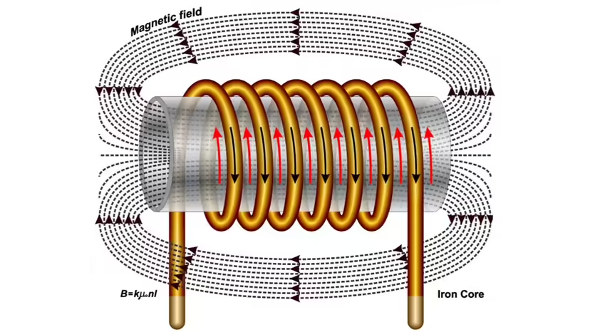
Solenoids are a common component in most electrical systems, and a symbol that you will encounter in many motor control diagrams. They are essentially electromagnets comprised of many turns of wire that serve as the heart of all electromagnetic motor starters and contactors. A solenoid turns electrical energy into linear mechanical movement. This movement is what facilitates the operation (opening and closing of the contacts) of the control circuit. In a motor starter solenoid (coil), the current that flows through the coils magnifies the strength of the magnetic field giving the “electromagnet” enough strength to close the contacts physically.
COMMON MOTOR CONTROL SYMBOLS :
If you want to know more, click here: How Solenoids Work | HowStuffWorks


Fouad A. Saad/Shutterstock
Automatic Versus Manual Control
Electrical circuits can be either automatic, manual or a combination of both. Automatic control circuits are derived from the Greek words “Autos” meaning self and “Matos” meaning animated. Automatic circuits are controlled autonomously and do not require input from a person to operate the system once they are set up. Manual control circuits, on the other hand, always involve a person to operate the system. The majority of motor control circuits are a combination of both automatic and manual control. Most systems are operated automatically but it is always a good idea to have manual control of a circuit for troubleshoot and safety purposes.
All electrical circuits can all be broken down to five basic components. They include the “power source” that supplies the circuit. The “conductors” that handle the flow of electricity. Some sort of control switch to make and break the flow of electrical current. The “load” that actually utilizes the electricity, and lastly some sort of “over current protection device” (OCPD) like circuit breakers and fuses used to protect the circuit in the case something goes wrong.
Looking Deeper
Within every electrical circuit you will have specific symbols that represent all of the basic components of the system. Think of these symbols as a type of language, with each individual symbol representing a specific word or meaning. Taken together, these symbols tell a story about how the circuit should operate (logic). Like any language, you first need to become familiar with what each symbol represents in order to be able to understand what the circuit should be doing and how it should be wired to accomplish the desired outcome.
Keep in mind
As you continue to work with and are exposed to reading and interpreting ladder diagrams you will become more proficient with the language of controls. Becoming fluent in this universal language will translate to a better understanding of the various systems you will potentially encounter as a commercial/industrial electrician.
Specialized schematic drawings depicting two vertical rails and horizontal rungs used to convey the logic of a control system.
Device comprised of an electric coil that changes the magnetic field created by electric current flow into linear mechanical movement.
An assembly consisting of many turns of wire wound together with the purpose of creating an electric magnet strong enough to be used to open and close sets of contacts. Referred to as the “heart” of a contactor or motor starter.

