Chapter 11: Reversing Motors
Chapter Overview
Chapter 11 will cover the specific requirements for reversing motors. Industry-standard procedures for safely and conveniently reversing the direction of motors will be discussed. Chapter information link.
- Switching any two leads will reverse the direction of a 3-phase motor, but reversing L1 and L3 on the line side of the motor starter is considered the industry standard.
- Reversing the electrical connections to a motor may be accomplished with manual reversing starters, drum switchers, magnetic reversing starters, PLCs, or motor drives.
Key points to remember:
- Limit switches are used in reversing circuits to provide over travel protection.
- Trouble shooting reversing circuits should begin in the control cabinet.
- There are two types of control wiring methods:
- Direct hard wiring: The oldest and most straightforward motor control wiring method used. In direct hard-wired systems, the control circuit is wired point to point where each component in the circuit is wired directly to the next component. Con: hard to reconfigure.
- PLC wiring: Allows for greater flexibility and circuit monitoring of a motor control circuit while also eliminating much of the wiring and components. Con: with the substantial initial cost of installation these systems are usually only feasible in large facilities that would need to be rewired frequently. Ex: General Motors manufacturing facility.
- Shaded pole motors cannot be reversed.
- Crossing dashed lines indicate a mechanical interconnection or interlock.
Reversing Motors
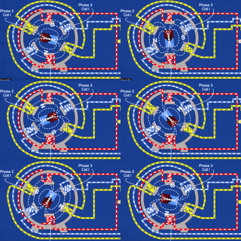
Being that motors are used for so many diverse applications, there are times and situations where the direction of rotation for a motor would need to be reversed as in the case with elevators or overhead doors. All motors can be made to spin in the opposite or “reverse” direction, except for shaded pole motors, by simply reversing the direction of current flow. This direction reversal can be as simple as interchanging two leads of any motor, although motors that are designed to be reversed typically utilize a reversing motor starter or dedicated drum switch.
Changing the rotation of a 3-phase motor
Motor Reversal methods
Single-phase motors can usually be reversed by swapping the two lead wires of the motor effect effectively switching the direction of current flow and thus the polarity of the starting winding. This process reverses the direction of the rotating magnetic field and causes the motor to spin in the opposite direction.
Three-phase motors can be reversed by simply interchanging or “swapping” the order of any two of the three phase conductors. While any two phases can be swapped, the rule of thumb is to specifically interchange the A and C phase conductors. The industry further clarifies by indicating not only which two phases to swap but also where the swap should take place at L1 and L3 on the line side of the motor starter.

Image source: www.captaincookelectrical.com.au
Interlocks provide a dedicated method to prevent the accidental reversal of motor rotation. A motor cannot run in forward and reverse at the same time so it is important to prevent the potentially catastrophic unwanted or premature reversal of any motor. Mechanical interlocks are shown in the diagram below as dashed interconnected lines. This is intended to show that the push buttons controlling the system are interconnected similar to a teeter totter where when one is up (open) the other has to be down (closed). Electrical interlocks are also shown below and are often used in conjunction with limit switches to provide further protection from the accidental reversal of any motor.

Image source: https://sosteneslekule.blogspot.com/2015/04/plc-implementation-of-forwardreverse.html
Keep in mind
Motors can also be “plugged” or intentionally reversed to rapidly slow their rotation. Plugging circuits reverse the polarity of the current flow and essentially use the motors counter electromotive force against itself to facilitate faster stopping times in emergencies or for intended control operations where more precise control of motor stopping times is needed.
Looking Deeper
Direct hard wiring is the oldest and most straightforward motor control wiring method used. In direct hard-wired systems, the control circuit is wired point to point, where each component in the circuit is wired directly to the next component. The main disadvantage here being the difficulty reconfiguring when changes are needed.
PLC wiring Allows for greater flexibility and circuit monitoring of a motor control circuit while also eliminating much of the wiring and components. The substantial initial cost of installation of these systems is usually only feasible in large facilities that would need to be rewired frequently. In the early 1970’s, General Motors manufacturing required the frequent rewiring of control systems every time the production line need to be changed when a new model came out. This ultimately facilitated the development of the first PLC systems that could be easily reprogrammed every time retooling was necessary.
A rotating switch that manually reverses the order of the motor leads thereby reversing the direction of the motor rotation.
(Programmable logic controller) Solid-state device that takes the place of more rudimentary motor starters and relays allowing for more seamless automation of control circuits.
Intentional reversal of a motor intended to facilitate the rapid stopping of motor rotation.

