
Chapter 1: Basic Electrical Theory and Electrical Quantities
Chapter Overview
Chapter 1 will cover basic electrical theory and electrical quantities. Understanding basic electrical theory as an electrician working around such a hazardous energy form is important. Understanding electrical theory will help in installing electrical systems not only properly but also safely.
Key points to remember:
- The number of valence electrons in the outer shell of an atom determines if the material will be a conductor, semi-conductor, or insulator.
- Electron flow theory is the most widely accepted theory and states: Current flows from – to +.
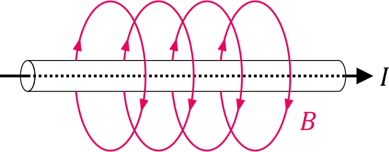
- Electromagnetism is the magnetic field produced when an electric current passes through a conductor.
- Ohm's law is the relationship between voltage, current, and resistance in a circuit.
Electrical Theory Review
Conductors are materials that are good at “conducting” electrical flow measured in amps (A), known commonly as electricity. The conductor’s ability to allow the flow of electrons is directly related to the amount of valence electrons present in the outer or “valence” shell of an electron’s atom. For example, silver is an excellent conductor since it only has one valence shell electron. This lone electron is more easily displaced from its orbit around the nucleus, hence its ability to facilitate the flow of current. Copper is another commonly used conductor as it contains two valence electrons, and it adequately facilitates current flow while also being cheaper and more abundant than better but less common and more expensive conductors like silver or gold.
Insulators are materials that contain a full 8 valence electrons in their outer shell which are not easily displaced from their orbit around the electron nucleus. This is the reason insulators resist the flow of electrical current. Glass, rubber and porcelain are all examples of materials that resist the flow of electrical current. This resistance (R), measured in ohms, to current flow is especially advantageous when applied to wires used for electrical circuitry where the inner conductor is insulated to protect people and property for the hazards that arise from the use of electricity.
Semi-conductors are just what they sound like, semi good at conducting electricity. The basic materials used for most semiconductor are germanium and silicon, which in their pure state do not have enough free electrons to support a useful amount of current flow. Therefore, their structure must be altered to make the crystal either more or less conductive. All semi-conductors contain four valence electrons, which makes them excellent candidates for the basic building blocks for all solid-state (digital) devices including photovoltaic (PV) cells. They are commonly “doped” with arsenic, boron, or gallium to alter their basic electrical properties to be either better or worse at conducting electrical current.
Doping, as it refers to semiconductor materials, is the act of changing the crystalline structure of a semiconductor material by adding impurities to alter its conductive properties. The final operating characteristics of the semi-conductors can be controlled through the number of impurities added to the basic crystalline structure of the individual semi-conductors. Due to the compact size, they inherently do not tolerate high levels of current flow as there are no moving parts to speak of.

P and N junctions
Electrical Circuits and Components
In any electrical circuit, not all the energy that is produced is utilized due to inefficiencies in the electrical system. This inefficiency is known as the power factor. Power factor is the ratio of true power and apparent power. It is the ratio of how much energy, or “true power” measured in watts (W), is actually used by the system. Apparent power, measured in volt-amps (VA), is the total amount of energy available. The power factor is determined by dividing the apparent power (VA) or total power supplied by the true power (W) that is actually consumed. Think of the power factor like a bag of chips. You pay for the full bag, but the bag is never full. In essence you are paying for the whole bag, but you only get to eat portion of what the bag promised.
Capacitors are electrical devices that store and discharge electrical current. They are comprised of two conductors separated from each other by a dielectric. Capacitors are commonly used to correct power factor and efficiency issues in large electrical systems that contain high inductance e.g. manufacturing plant with a large number of inductive loads like motors. The capacitors are used to effectively cancel out the high inductance caused by large motor loads. This in turn brings the system back into balance and ultimately leads to higher efficiency. This higher efficiency is advantageous to the power utility as they do not have to supply a large amount of power that the consumer is not utilizing by still must pay for, just like paying for the entire bag of chips but only getting to eat a fraction of what the bag could potentially hold.
What is Power Factor
Looking Deeper
Electricity or the flow of electrical current measured in ampacity (A) is inherently dangerous. This is especially true for anyone working in the electrical industry. Knowing the difference between an insulator and conductor could ultimately save your life. This could translate to simply knowing what is safe to touch and where to never stand while working in the field. For example, never pick up a capacitor before first safely discharging it with a properly sized resistor to prevent an unwanted shock. Keep in mind the severity of any shock is affected by your resistance, the amount of current, the path the current takes and the duration for which you are exposed to the current. Remember that your safety is ultimately your responsibility.
Keep in mind
Ohm’s law is used to find unknown values in an electrical circuit, but it is also useful for understanding the relationship between various parts of any electrical system for the purposes of installing, maintaining or trouble shooting.
The most widely accepted theory used by electricians that states current flows from negative to positive polarity.
The resultant magnetic field produced any time electric current passes through a conductor.
Ohm’s law states that current in a circuit is proportional to the voltage and inversely proportional to the resistance. Any unknown value can be determined when the other two values are known.
The flow of electrical current in an electrical circuit measured in amperes (A).
Also known as solar cells, are devices that turn sunlight into electricity using the photovoltaic effect.
Refers to the process of changing the crystalline structure of a semiconductor material by adding impurities to alter its conductive properties.
this ratio of true power to reactive power indicates the efficiency of any given electrical system and is directly related to a phase shift of voltage and current.
